Ask anyone who has spent time in a wind tunnel or a turbomachinery test cell, and they will tell you the same thing — getting good data starts with having the right probe in the right place. Three-hole probes have been doing this job for decades. One port faces forward to capture total pressure, and two side ports sit at roughly 45 degrees off the axis to pick up the directional component. Combine those three readings with the right calibration, and you can recover both the local flow angle and the velocity magnitude at that point in the flow field.
The concept is straightforward. The engineering is not — at least not when you are operating outside the comfortable range of a catalog probe.
Consider the realities of real-world testing programs. A compressor rig might run at inlet Mach 0.8 with tip clearance gaps under two millimeters. A turbine nozzle guide vane test could see gas temperatures pushing 600°C in a passage where a standard 3 mm probe simply does not fit. An intake distortion survey on a turboprop engine needs a probe long enough to reach the measurement plane but stiff enough to resist vibration at cruise RPM. No single off-the-shelf design covers all of these cases. That is where the custom route comes in.
At WINDTUNER, we have built our custom probe business around a six-stage process that runs from the first conversation with the test engineer through to post-installation support. Each stage exists for a reason — mostly because we have learned the hard way what goes wrong when you skip one.
It Starts with Getting the Requirements Right
This sounds obvious. In practice, it is where most problems originate.
When a customer comes to us with a probe request, we do not just ask for the diameter and the length. We walk through a fairly detailed specification sheet that covers head geometry, tip profile, expected Mach number range, total temperature envelope, the test medium (air, combustion gas, synthetic mixtures), mounting type, sealing requirements, and signal routing. Every one of these parameters feeds directly into a downstream decision.
We have seen what happens when this step gets rushed. A customer once specified a maximum temperature of 350°C but did not mention that the probe would see cyclic thermal loading — heat up, cool down, repeat for hundreds of cycles. The stainless steel we selected based on the static temperature spec held up fine thermally, but the braze joints between the sensing head and the pressure tubing developed microcracks after roughly 200 cycles. If we had known about the thermal cycling during the initial spec review, we would have recommended a nickel-based superalloy with a different braze alloy, and the probe would still be in service today.
The takeaway is simple. Spend the time upfront. A thorough requirements review takes maybe a few extra days of back-and-forth. Redesigning and rebuilding a probe that fails in service takes months.
Designing the Sensing Head
Once we know what the probe needs to survive, the next question is how to make it measure well.
The baseline geometry — one forward-facing port plus two side ports at ±45° — works well across a wide range of conditions. But "works well" is not the same as "works optimally," and that distinction matters when you are trying to resolve flow angles to within a fraction of a degree.
Probe diameter is usually the first trade-off we work through. Go smaller, and you disturb less of the flow — important in boundary layers, thin annular passages, and anywhere the probe blockage ratio matters. But smaller also means smaller sensing holes, which means lower differential pressures at the transducer and more noise in the data. For a 1.5 mm diameter probe, the sensing holes might be only 0.2 mm across. At that scale, even a small burr on the hole edge represents a meaningful fraction of the flow area.
The side-port angles can also be adjusted. If you know the flow is going to stay within ±15° of the probe axis, there is no reason to use a wide-angle configuration. Narrowing the angle from 45° to, say, 35° or 30° gives you better sensitivity in the range you actually care about. The cost is reduced range — but if you never need to measure beyond ±15°, that cost is zero.
Then there is the positioning of the holes themselves. The angular spacing between the two side ports needs to be symmetric within a few micrometers at the hole edges. Any asymmetry means the probe reads a different angle when yawed left versus yawed right, which is a systematic error that no amount of data post-processing can fully correct.
Picking the Right Material
Material selection in probe design is not just about temperature — although temperature is usually the first filter we apply.
For anything at ambient conditions up to about 200°C, austenitic stainless steels like 304 and 316 are hard to beat. They are strong enough, they machine cleanly, they take a braze well, and they do not cost a fortune. Most subsonic wind tunnel probes we build use 316 stainless steel for exactly these reasons.
Above 200°C, the picture changes. Stainless steel starts to lose useful strength, and if there is any sulfur or other corrosive species in the flow, oxidation rates climb quickly. Titanium alloys (Ti-6Al-4V being the most common in our shop) hold up well to around 400–450°C and have the added advantage of being lighter, which matters for long probes that need to resist vibration. Nickel-based superalloys — Inconel 718, Hastelloy X, and similar grades — extend the range further, typically up to about 800°C depending on the exact alloy and the exposure duration.
For the really extreme cases — gas turbine hot-section testing, afterburner diagnostics, scramjet isolator surveys — cobalt-based alloys like Haynes 188 or Stellite 6 offer temperature capability above 1000°C with good resistance to thermal cycling and hot corrosion. The trade-off is machinability. These alloys are abrasive and work-harden during machining, which means slower cycle times and higher tooling costs. You pay for the temperature capability, and you pay again during manufacturing.
We also consider weldability explicitly during material selection. The sensing head needs to be joined to the pressure tubing that runs the length of the probe stem, and that joint has to hold under thermal and mechanical loading. Some alloys braze beautifully; others fight you every step of the way. Choosing a material that machines well but cannot be reliably brazed to your pressure tubing is not a good deal, no matter how attractive the spec sheet looks.
Making It: Where Design Meets Reality
I am going to be blunt here. Getting a three-hole probe manufactured to the required tolerances is genuinely difficult.
Think about what is involved. You have a cylindrical stem that might be 1.5 mm in diameter and 300 mm long. The outer diameter needs to be held to within a few micrometers of nominal, the straightness needs to be better than 0.05 mm over the full length, and the surface finish needs to be smooth enough that it does not create its own boundary layer disturbance. At the tip, three holes — each perhaps 0.2 mm in diameter — need to be positioned with angular accuracy of a few tenths of a degree, drilled to consistent depth, and finished without burrs or surface irregularities.
Traditional CNC machining can handle most of this, but it has limits. The internal passages that route pressure signals from the sensing holes to the tubing at the back of the probe are particularly challenging. In a conventional build, these are often drilled as through-holes and then plugged, which introduces extra joints and potential leak paths.
That is a big part of why we adopted additive manufacturing as part of our production process. Metal additive processes — specifically laser powder bed fusion in our case — allow us to build the internal pressure routing into the probe body as a single piece. No secondary drilling, no plug fittings, no extra braze joints. The sensing holes are then finished with precision CNC post-processing to hit the final geometry and surface quality specs.
We developed this hybrid approach in close cooperation with our German technology partners, who brought decades of experience in micro-scale aerodynamic probe manufacturing. The result is a process that consistently delivers probes where the as-built geometry matches the design intent to within micrometer-level tolerances — something that is very difficult to achieve with machining alone.
Calibration: The Step You Cannot Afford to Skip
A probe that has been manufactured perfectly is still not ready to use. You need to calibrate it.
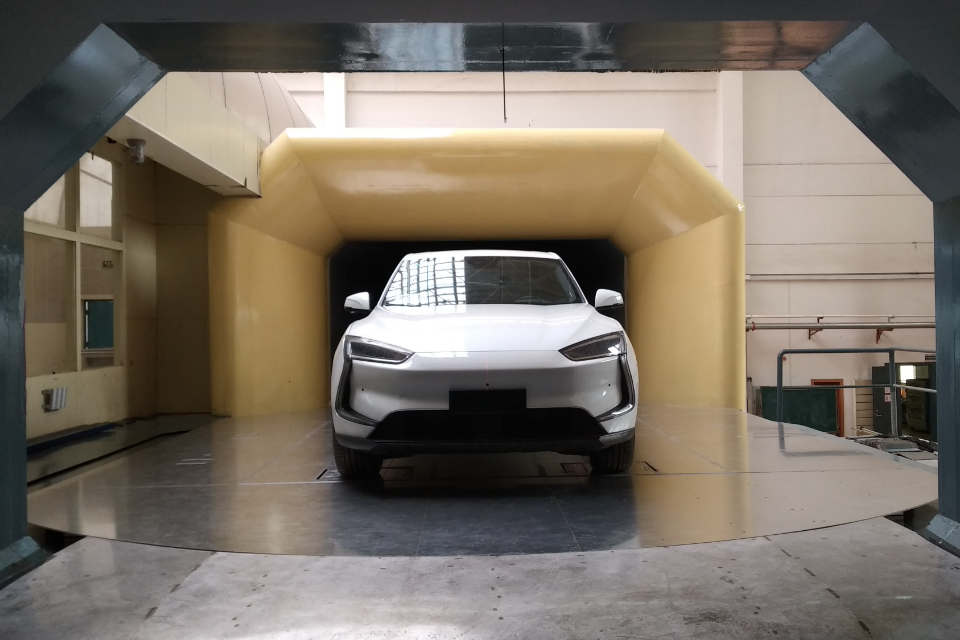
The calibration process works like this. The probe goes into a calibration wind tunnel — a facility where you can precisely control the freestream Mach number and the angle of attack seen by the probe. At each combination of Mach and flow angle, you record the pressures from all three sensing ports. Repeat this across a grid of conditions (typically something like five to seven Mach numbers and flow angles from -30° to +30° in 2° or 5° increments), and you end up with a dataset that maps port pressures to flow parameters.
From this dataset, you derive calibration coefficients — essentially mathematical functions that let you convert the three raw pressure readings into flow angle, dynamic pressure, and Mach number during an actual test. The quality of those coefficients depends entirely on the quality of the calibration facility.
A calibration tunnel with poor flow uniformity will give you coefficients that contain errors from the facility itself, not from the probe. If the tunnel cannot hold Mach number steady to within ±0.005, or if the angular positioning system has backlash of more than a few hundredths of a degree, the resulting coefficients will propagate those errors into every measurement the probe ever makes. There is no way to fix this in post-processing. The calibration is only as good as the facility that produced it.
Our calibration center in China operates three dedicated calibration wind tunnels. We were the first privately operated calibration wind tunnel laboratory to earn CNAS accreditation, which means our calibration results are traceable to national measurement standards. Every custom probe we ship has been through the full calibration sequence in these tunnels, and the customer receives the complete calibration dataset along with the probe.
Delivery and What Comes After
The probe, the calibration report, and the installation guide all go out together. That is the baseline deliverable.
But in practice, a lot of our customers need more than that. Installing a probe into a turbine rig at 500°C is not the same as sliding it into a room-temperature wind tunnel. There are thermal expansion considerations, sealing challenges at elevated temperature, and questions about how to route the pressure tubing from the measurement plane to the transducers outside the test section. We provide installation guidance and, when needed, on-site support to help get the probe set up correctly.
We also offer periodic recalibration. Probes drift over time — not because the geometry changes, usually, but because repeated thermal cycling, handling, and exposure to the test environment can subtly alter the surface condition of the sensing holes or the integrity of internal passages. A recalibration every 12 to 24 months, depending on usage, is a reasonable interval for most applications.
Putting It All Together
A custom three-hole probe is a deceptively simple-looking device that requires an enormous amount of engineering judgment at every stage of its creation. The specification has to be right. The design has to balance competing demands. The material has to match the environment. The manufacturing has to hit tolerances that are measured in micrometers. And the calibration has to be performed in a facility that is itself held to rigorous standards.
Cut any one of those corners, and the probe will still look fine on the outside. It just will not give you data you can trust.
That is the reason we maintain the entire chain in-house — design, material selection, manufacturing, and calibration — rather than outsourcing any part of it. When something goes sideways at any stage, we catch it before it ships. And when a customer calls with a tricky application that does not fit any standard template, we have the depth to work through it together.
If you have a probe requirement that goes beyond what a catalog can offer, we are happy to talk through it.
- Popular Tags:pneumatic probes3D PrintingaerodynamicsturbomachineryTurbo ExpoPressure ScannersDroneAirspeed Probe Pressure CalibrationFive hole probesEthernet Intelligent Pressure ScannersEthernet Intelligent Pressure Scanners System: Importance of purge function to Ethernet IntelligentFlow Field MeasurementWindtuner Pressure Scanner Gas turbineEthernet Intelligent Pressure Scanners Application Industry Analysis Five-Hole Probe AerodynamicsCustom Five-hole Probe Flow field
How a Custom Three-Hole Probe is Made: Inside the Full Development Cycle
04 Jun 2026