This isn't a product quality issue. It's an application mismatch problem.Understanding why requires looking at each test type on its own terms.
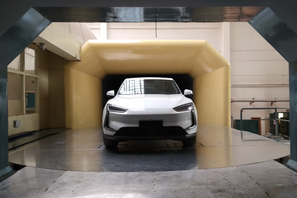
Configuration Sweeps in the Low-Speed Tunnel: When You Need to Move Fast
High-lift development work is, by nature, iterative. A team optimizing flap and slat geometry might run twenty or thirty configurations in a single week — each at multiple angles of attack, each generating a new set of surface pressure distributions that feed back into the design loop. The pressure measurement system lives inside that loop.
Under these conditions, the bottleneck isn't accuracy. Modern scanning valves are accurate enough for this work. The bottleneck is throughput: how quickly can you acquire clean data across every tap, finish the current run, and prepare for the next one? A system with limited channel count forces you to reposition hardware between runs. A slow sampling rate stretches acquisition time. Either of these inefficiencies compounds across a 30-configuration matrix and can add days to a program timeline.
The WINDTUNERStandard Edition addresses this through 16 individually calibrated sensors per module with a 500 Hz per-channel sampling rate, and the ability to cascade multiple units for larger tap arrays. For teams running dense configuration matrices, that combination of density and speed is what determines whether the test program stays on schedule.

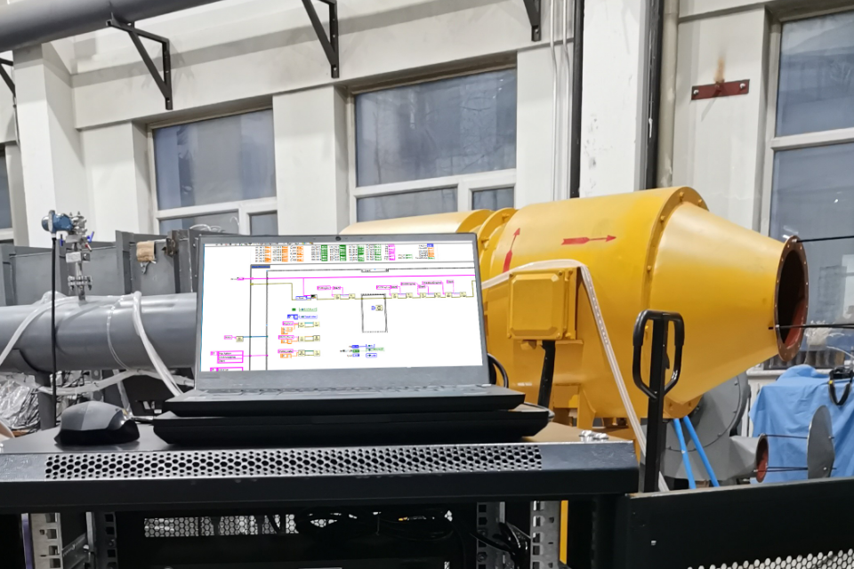
Inlet Total Pressure Surveys: A Different Kind of Precision Problem
The metrics that define inlet performance — total pressure recovery and distortion index — are calculated from the spatial distribution of total pressure across the inlet exit plane. Typically this means a raked probe array, often arranged in a specific pattern prescribed by ARP1420 or similar standards, feeding into a scanning valve that acquires all channels in a single simultaneous burst.
What makes this test type unusual is that the absolute accuracy of any individual channel matters less than the consistency between channels. If one channel reads 0.3% high and another reads 0.3% low, the distortion calculation absorbs that error directly. You can have a valve with excellent zero-point calibration and still produce distortion maps that don't match the physical flow field — simply because of uncorrected inter-channel offsets.
This is why WINDTUNER subjects each unit to cross-channel linearity and uniformity calibration before shipment, rather than relying on module-level specifications alone. The goal is to ensure that when 16 channels are reading simultaneously, they're reading the same flow conditions the same way.
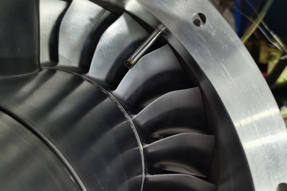
Turbomachinery Rigs: The Problem Nobody Talks About in Spec Sheets
Compressor and turbine test programs present a challenge that has nothing to do with signal quality: where do you put the hardware?
Blade row passages are tight. The space available between a compressor stage and the downstream measurement plane is often measured in millimeters of clearance. Instrumentation that works perfectly in a large-scale external aerodynamics tunnel can become physically impossible to install in a rotating machinery rig. Probe tubing must be routed through access ports that were designed for other purposes. Connector panels end up in locations that are awkward to reach during a test run.
The compact integrated housing of the WINDTUNER Standard Edition was developed with these installation constraints as a primary design consideration, not an afterthought. Equally important for turbomachinery applications is the built-in pneumatic valve circuit that enables in-situ switching between measurement and calibration modes. On a rig where the test section is difficult to access, being able to run a zero-point check without dismantling surrounding hardware is a practical necessity, not a convenience feature.
Unsteady Measurements: Where Frequency Response Actually Matters
Most of the tests described above involve nominally steady flow — the pressure field changes slowly enough that quasi-steady acquisition is a reasonable assumption. Unsteady testing breaks that assumption entirely.
In separated flow studies, buffet onset characterization, or pressure fluctuation surveys in high-frequency environments, the flow field changes faster than the acquisition system can track if the system isn't designed for it. The result is phase lag and amplitude attenuation — the measurement system reports what the pressure was, not what it is, and reports it at a lower amplitude than the actual signal. Data that looks clean can be significantly wrong.
For these applications, frequency response bandwidth has to be evaluated explicitly against the expected frequency content of the test. It's one of those specifications that rarely drives the conversation during initial procurement discussions, and then becomes the central issue when the test program starts.
The Multi-Test Reality
Research institutions and industrial test facilities rarely run just one type of program. The same facility that runs inlet surveys in the spring may run high-lift configuration work in the fall and support a turbomachinery program in between. Buying a valve optimized for a single application is a reasonable strategy only if your test calendar stays perfectly consistent — which it usually doesn't.
The WINDTUNERStandard Edition is built around a balanced specification profile: ±0.05% FS accuracy, 500 Hz per-channel sampling, operating range from −30°C to +60°C, calibrated inter-channel consistency, and a physical form factor that accommodates varied installation conditions. No single number in that list represents the highest available performance in its category. But across the combination of test environments where a serious research organization operates, that balance tends to translate into broader utility than a system that excels in one dimension at the cost of others.
The engineers who get the most out of their measurement equipment are usually the ones who understand what each test type actually needs — and match their selection to that understanding rather than chasing the biggest number on the spec sheet.