
This is why the pressure scanning valve has become an essential part of modern multi-point pressure measurement. Its role appears straightforward: connect many pressure lines to a measurement system and acquire them in an orderly sequence. Yet the practical value of the instrument goes much further. A properly selected scanning system can reduce plumbing complexity, improve test repeatability and give engineers a clearer view of how pressure is distributed across a component or flow field.
The distinction matters. Engineers rarely need a single pressure value. They need a pressure map.
One Instrument, Many Measurement Points
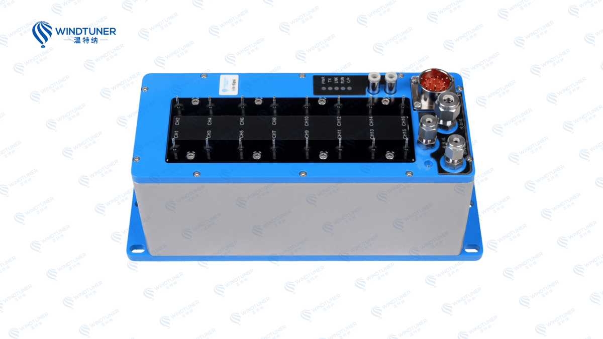
A pressure scanning valve allows multiple pneumatic inputs to be measured through a compact, organized acquisition architecture. Each channel may be connected to a pressure tap, a pitot or total-pressure probe, a multi-hole probe, a pressure rake or another pneumatic sensing point.The system switches or scans among these channels while the associated transducer and acquisition electronics convert the pneumatic signals into usable data. Depending on the configuration, reference pressure, purge functions and calibration paths may also be incorporated into the measurement process.
This arrangement is particularly useful when the alternative involves dozens—or hundreds—of individually managed pressure connections. More tubing does not merely occupy space. It creates more opportunities for leaks, incorrect routing, inconsistent tube lengths and maintenance errors.
A scanning valve does not remove the need for careful test preparation. It makes that preparation manageable.
Why Wind-Tunnel Testing Depends on Pressure Scanning
Wind tunnels remain one of the clearest applications for pressure scanning valves. A model of an aircraft wing, vehicle body, turbine blade or industrial structure may contain a dense network of surface pressure taps. Each tap represents only a small point on the model. Taken together, however, they reveal the pressure distribution that drives aerodynamic forces and exposes flow separation, loading changes and local disturbances.Consider an airfoil test. Pressure taps placed along the upper and lower surfaces allow engineers to reconstruct the pressure coefficient distribution. That distribution can be integrated to estimate aerodynamic loading and compared across angles of attack, flow speeds or model configurations.
The scanning valve sits between the model and the data system, but its influence extends to both. Its channel capacity affects how the model is instrumented. Its pressure range must suit the expected test conditions. Its scanning speed determines whether a complete pressure map can be acquired within a stable operating period. Its pneumatic characteristics influence how quickly each channel settles.
The valve, in other words, cannot be selected after the experiment has already been designed. It belongs in the design conversation from the beginning.
A Critical Role in Turbomachinery Development
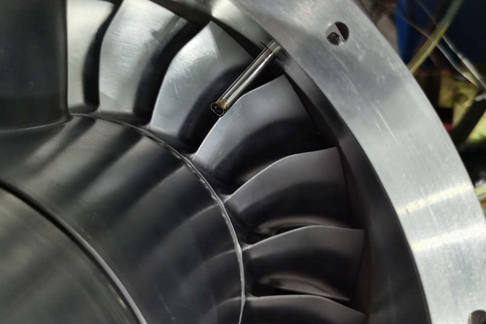
Pressure measurement becomes more demanding inside compressors, turbines, fans and pumps. The available installation space is limited, the geometry is complex and pressure gradients can change substantially over short distances.Engineers may use pressure rakes or multi-hole pneumatic probes to examine flow at an inlet, outlet or intermediate station. These instruments often contain several pressure ports, and a single survey may involve numerous radial, circumferential or traversing positions. A pressure scanning valve enables those ports to be recorded through a structured channel system.
The resulting measurements can help engineers evaluate total-pressure loss, flow uniformity, component loading and the effects of wakes or secondary flows. When multi-hole probes are used with appropriate calibration, the pressure data can also support the calculation of flow direction and velocity-related quantities.
Here, channel identification is not clerical detail. If two pneumatic lines are reversed, the resulting flow-angle calculation may look plausible while still being wrong. A professional measurement system therefore requires disciplined channel mapping, traceable configuration records and verification before the test begins.
Automotive, Building and Industrial Applications
The same principle applies well beyond aerospace laboratories.Automotive developers use distributed pressure measurements to study the flow around vehicle bodies, cooling passages, underbody structures and aerodynamic components. A pressure map can show where design changes alter loading or where airflow is being diverted in an unintended way.
In civil and architectural testing, pressure taps distributed across a building model can help researchers examine wind loads on façades, roofs and structural features. Industrial airflow studies may use multi-point pressure measurements in ducts, ventilation equipment, heat exchangers and rotating machinery.
These applications differ in scale and operating conditions, but they share a common requirement: many pneumatic signals must be acquired without losing control of channel identity, range, stability or timing.
That is the business case for pressure scanning. It converts a large collection of pressure lines into a measurement system that engineers can audit.
Speed Is Important, but Settling Time Is Often More Important
Pressure scanning systems are frequently compared by scan rate. The figure is useful, but it can be misleading when considered alone.A pneumatic measurement does not respond instantaneously. Tube length, internal diameter, pressure volume, restrictions and the characteristics of the measured flow all affect response. After a valve changes channels, the system may require time to settle before the reading represents the actual pressure with sufficient confidence.
This creates a practical trade-off. Scanning too slowly wastes tunnel time and may miss changes in operating conditions. Scanning too quickly can produce readings that reflect pneumatic transients rather than stable channel pressures.
A sound configuration therefore considers the complete pneumatic path—not merely the switching mechanism. Tube routing, connection quality, expected pressure range and the required measurement bandwidth belong to the same engineering calculation.
What a Professional Selection Process Looks Like
Choosing a pressure scanning valve begins with the experiment, not the catalogue.Engineers first need to define the number of pressure inputs, expected pressure range, reference-pressure arrangement and required acquisition speed. They must also consider whether the measurement is steady, slowly varying or genuinely unsteady. Environmental conditions, available installation space, tubing dimensions and integration with the data-acquisition platform can further narrow the choice.
Calibration strategy deserves equal attention. Zero checks, reference verification, leak testing and channel validation should be planned before the first formal run. Purge capability may be important where contamination or moisture can reach the pressure lines. In tightly packaged installations, serviceability can be as consequential as nominal performance.
A system with impressive specifications may still be unsuitable if it is difficult to connect, verify or maintain in the actual test environment.
WINDTUNER’s System-Level Approach
WINDTUNER approaches pressure measurement as a complete engineering chain. The pressure scanning valve is one part of that chain, alongside pneumatic probes, pressure tubing, channel configuration, calibration procedures, data acquisition and the physical conditions of the test.This system-level view is especially important when scanning valves are combined with pressure rakes or multi-hole probes. Probe geometry determines where pressure is sampled. Manufacturing quality affects the consistency of the pressure ports. Calibration establishes how measured pressures relate to the required flow quantities. The scanning system must then preserve those signals and deliver them to the acquisition platform in a controlled manner.
WINDTUNER’s work in flow-field measurement covers the design, manufacture and wind-tunnel calibration of pneumatic probes for low-speed, subsonic and supersonic conditions. That background shapes a practical understanding of pressure scanning applications: the value of an instrument is determined by the reliability of the entire measurement path.
Rather than treating channel count or scanning speed as isolated selling points, WINDTUNER considers the operating range, test layout, probe arrangement, pneumatic response and data objectives together. This is the difference between supplying a component and supporting a measurement task.
Reliable Data Begins Before the First Scan
Pressure scanning valves have made large-scale pneumatic measurement faster and more compact. They have not made it automatic.Reliable results still depend on decisions made before the test: where pressure is sampled, how tubing is routed, how channels are identified, how the system is calibrated and how much settling time is allowed. When these details are handled well, hundreds of individual pressure signals become a coherent account of the flow.
That account can guide an aerodynamic redesign, expose a loss mechanism or confirm that a component performs as intended. The valve may remain out of sight during the test. Its contribution is visible in the data—and in the engineering decisions that follow.