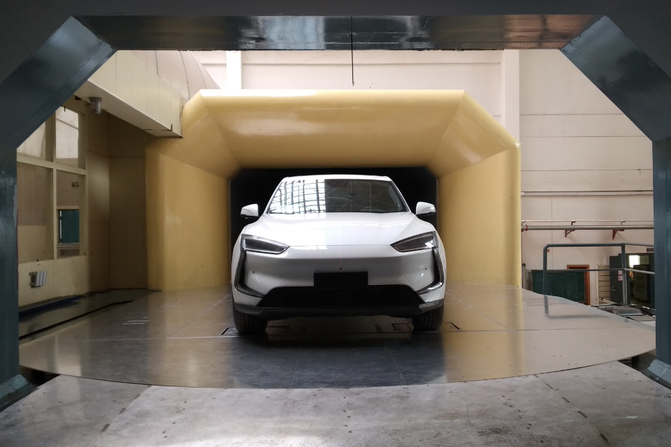
When a wind tunnel test section holds a compressor cascade, a turbine vane row, or a heat exchanger bundle, the flow field downstream is anything but uniform. Engineers need to know exactly what happens: where velocity peaks, where flow separates, and how angles shift across the passage. A single measurement point tells you nothing about the spatial structure. That is why five-hole probes exist, and why they become even more valuable when paired with automated traversing hardware.

The Core Hardware: Five-Hole Probe Meets Traverse System
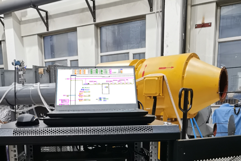
A five-hole probe measures total pressure, static pressure, and two flow angles in one shot, giving engineers the three velocity components at a single measurement point. But a single point is rarely enough. To map the full passage, the probe needs to move. Windtuner builds the five-hole probe into a traverse system that combines an electric actuator with a motion controller. The actuator positions the probe at programmed coordinates inside the test section, while the pressure scanner captures data at each location. The result is a grid of measurement points that reconstructs the flow field with the spatial resolution the engineer defines.
Every probe head comes from micron-level 3D metal printing, so angle response curves stay consistent across production units. Each five-hole probe then goes through calibration in our CNAS-accredited wind tunnel. The calibration data feeds directly into the measurement chain, and WindLabX is a reliable tool when it comes to converting raw pressures into velocity vectors.
What Automated Traversing Changes
Manual probe positioning limits resolution and throughput. An engineer sets the probe by hand, notes the position, takes readings, then repeats. This process takes hours and positioning errors creep in at every step. Windtuner automates that entire loop. The motion controller drives the actuator along a programmed path, the pressure scanner samples at 500 Hz at each stop, and WindLabX logs every data point with its position tag.
A typical turbomachinery cascade test runs a five-hole probe across sixty or more measurement points in the exit plane. With the automated system, the full traverse finishes in under fifteen minutes without an engineer in the loop. The probe covers pitchwise and spanwise coordinates that the test plan requires, and the dataset carries position accuracy from the actuator rather than hand measurements.
The pressure scanner handles the other half of the signal chain. Its 24-bit A/D conversion resolves the small pressure differences that define flow angles near separation zones, and the +-0.05% FS accuracy holds across the temperature range inside the tunnel. IEEE1588V2 time synchronization keeps pressure data from multiple scanner channels aligned to the same time base. That matters when the probe moves fast enough that flow conditions shift between measurement points.
From Raw Pressures to a Mapped Flow Field
Raw pressure values are not the final product. WindLabX takes the calibrated pressure signals from the scanner, applies the five-hole probe calibration coefficients, and computes total pressure, static pressure, Mach number, velocity, and both angular components at every traverse point. The software then maps these values onto a contour plot that shows exactly how the flow behaves across the passage.

Windtuner's WindlabX Software in Operation
This flow field mapping module within WindLabX turns what used to be a post-processing task into an output the engineer sees during the test run. If the contour shows a separation bubble forming at a particular span location, the engineer adjusts the test matrix on the spot rather than discovering it days later in the office.
Clients running engine inlet distortion tests, turbomachinery cascade experiments, and wind tunnel exit uniformity surveys have adopted this automated approach. It delivers a complete spatial picture in the time it used to take for a single line traverse.
Repeatable Data from an Integrated System
The advantage of keeping probe, actuator, scanner, and software within the same design loop is traceability. The same data structure holds every calibration coefficient, every actuator coordinate, and every pressure reading. When a client reruns a test three months later, the system reproduces the same traverse path with matching sampling times and calibration state. That repeatability is what separates data that advances a design from data that raises more questions.
Windtuner calibrates every five-hole probe in our own calibration wind tunnels, certifies each pressure scanner against CNAS-traceable standards, and tests the full traverse system before delivery. The system arrives as a coordinated set of instruments, not a collection of parts the engineer needs to integrate and debug on their own.