
A 3-hole probe uses the pressure responses at three ports, together with calibration data, to calculate flow velocity and flow angle in one plane within its calibrated range. It is used for two-dimensional flow measurements during research and development, where the direction of interest lies in a particular plane. WINDTUNER offers custom 3-hole probes, calibration, and pressure acquisition equipment to match probe dimensions and measurement range to the test and its installation constraints.
How the three ports respond to airflow
A common three-hole head has a center port and two side ports arranged in the same measurement plane. The ports face different directions, so each responds differently to the air passing over the head. As the incoming flow turns relative to the probe, the relationship between the side-port pressures changes. That response provides the basis for determining flow direction.
The pressure at one port cannot simply be read as a flow angle. Head geometry, port arrangement, and flow conditions all affect the response. The measurement system uses calibration relationships for the particular probe to convert the port pressures into flow angle and other parameters. The three ports supply pressure information; acquisition equipment and data processing are still needed to calculate the results.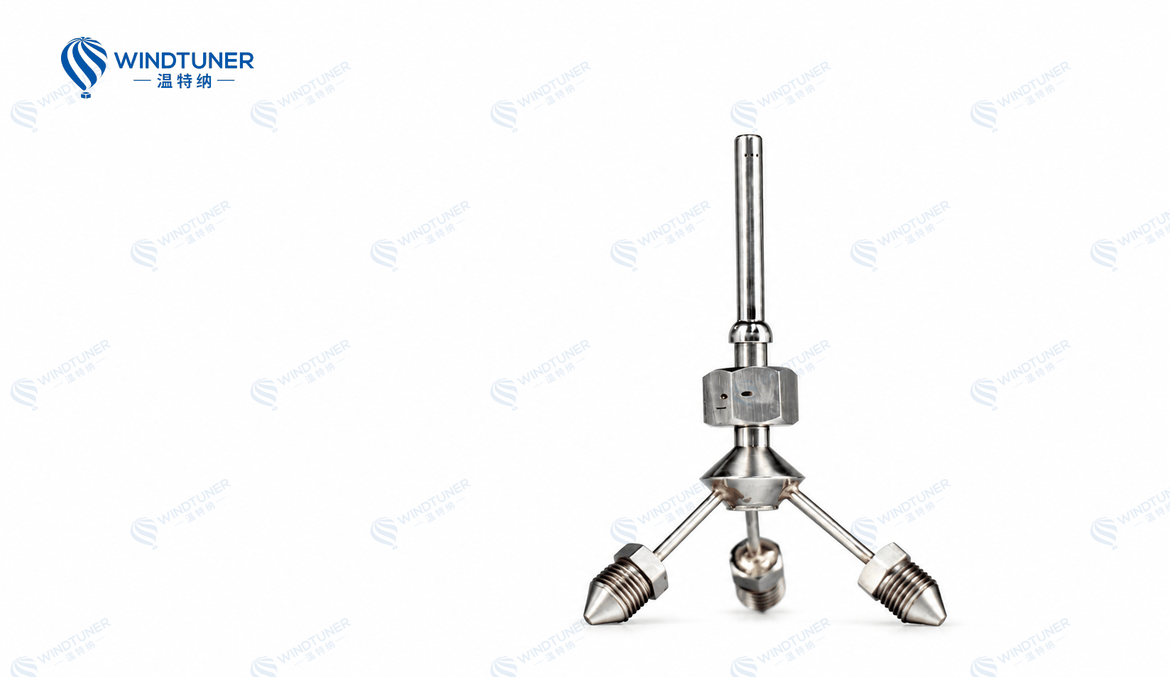
The pressure at one port cannot simply be read as a flow angle. Head geometry, port arrangement, and flow conditions all affect the response. The measurement system uses calibration relationships for the particular probe to convert the port pressures into flow angle and other parameters. The three ports supply pressure information; acquisition equipment and data processing are still needed to calculate the results.
Calibration links pressure readings to flow parameters
During calibration, the probe is placed in airflow under known conditions. Speed and the angle between the head and the flow are varied over a specified range while the port pressures are recorded. The resulting calibration relationships allow pressure responses from a test to be converted into the relevant flow parameters. Actual operating conditions must fall within the valid calibration range for that probe.
WINDTUNER offers pneumatic probe calibration services and can discuss a calibration plan for the intended conditions. If the head is altered or damaged, the suitability of its existing calibration data needs to be reassessed. A value still appearing in the software does not, by itself, validate a calculation made outside the calibrated range.
WINDTUNER offers pneumatic probe calibration services and can discuss a calibration plan for the intended conditions. If the head is altered or damaged, the suitability of its existing calibration data needs to be reassessed. A value still appearing in the software does not, by itself, validate a calculation made outside the calibrated range.
Align the measurement plane with the test
A 3-hole probe measures flow direction changes in one plane. Install it with that plane aligned to the deflection you want to study, and establish the reference direction used to define the flow angle. Otherwise, even steady readings can be difficult to relate to the physical direction of the flow in the test.
In a curved passage or downstream of a model, first consider whether the flow varies mainly within the intended plane. Significant out-of-plane flow calls for a closer assessment of whether a 3-hole probe is suitable, or whether a probe that measures flow angles in two directions is needed. The choice depends on the flow parameters required as well as whether the head fits in the available space.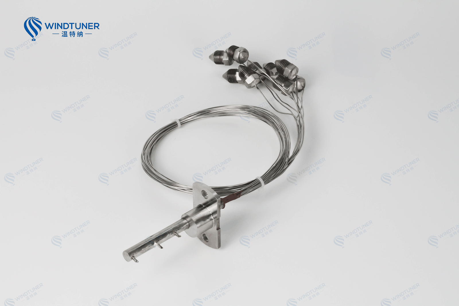
In a curved passage or downstream of a model, first consider whether the flow varies mainly within the intended plane. Significant out-of-plane flow calls for a closer assessment of whether a 3-hole probe is suitable, or whether a probe that measures flow angles in two directions is needed. The choice depends on the flow parameters required as well as whether the head fits in the available space.
Connect the probe to pressure acquisition equipment
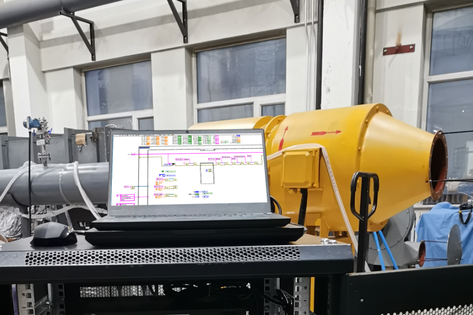
Pressure from each port is transmitted through internal passages and tubing to the pressure acquisition equipment. Once the pressures have been recorded, calibration data are used to calculate the flow parameters. WINDTUNER offers pressure scanners and measurement and control software; connections, ranges, and calculation settings should be confirmed for the test. Check the tubing connections, seals, and passages before taking measurements.
To examine changes across a section, take readings at a series of probe positions and record the location and operating conditions for each one. A 3-hole probe measures local flow at its head, so a single reading cannot describe the distribution across the whole section. With the required parameters, measurement locations, and expected flow range defined, WINDTUNER can discuss the probe structure, calibration, and acquisition setup.
To examine changes across a section, take readings at a series of probe positions and record the location and operating conditions for each one. A 3-hole probe measures local flow at its head, so a single reading cannot describe the distribution across the whole section. With the required parameters, measurement locations, and expected flow range defined, WINDTUNER can discuss the probe structure, calibration, and acquisition setup.