
Before arranging probe calibration, describe the probe's construction, its intended operating conditions, and the measurements you need. Calling it a three-hole probe or five-hole probe is usually not enough to define the work. WINDTUNER provides aerodynamic probe calibration and can discuss the calibration range in relation to the probe and the test. Preparing the following information before sending a probe in helps reduce follow-up questions and makes it easier to use the results in later measurements.

Describe the Probe and Its Condition
Start with photographs or a drawing that shows the probe head shape, number of pressure ports, head dimensions, and stem construction. The size of the head and shape of the stem affect how the probe can be mounted for calibration. A dimensioned drawing helps establish the space needed and whether the head can be oriented as planned.
Describe any impact damage, deformation, repairs, or blocked pressure ports, including where the problem occurred and what was done about it. This helps with inspection before calibration, which establishes the probe's pressure response under specified conditions. Its current condition needs to be checked to determine whether it is ready for calibration or requires further attention first.
Describe any impact damage, deformation, repairs, or blocked pressure ports, including where the problem occurred and what was done about it. This helps with inspection before calibration, which establishes the probe's pressure response under specified conditions. Its current condition needs to be checked to determine whether it is ready for calibration or requires further attention first.
Specify the Speed and Flow-Angle Range
Calibration conditions should match the conditions in which the probe will be used. State the intended velocity or Mach number range, whether several speed conditions need to be covered, and how the flow direction may vary. If a test plan already exists, share the relevant operating ranges. There is no need to make unsupported estimates just to fill in a specification.
For a five-hole probe or another probe used to measure three-dimensional flow, specify the flow-angle range in each of two perpendicular planes. The zero position and positive and negative directions also need to be clear. An 'angle range' without those definitions can leave the calibration orientation inconsistent with the convention used in the measurement calculations.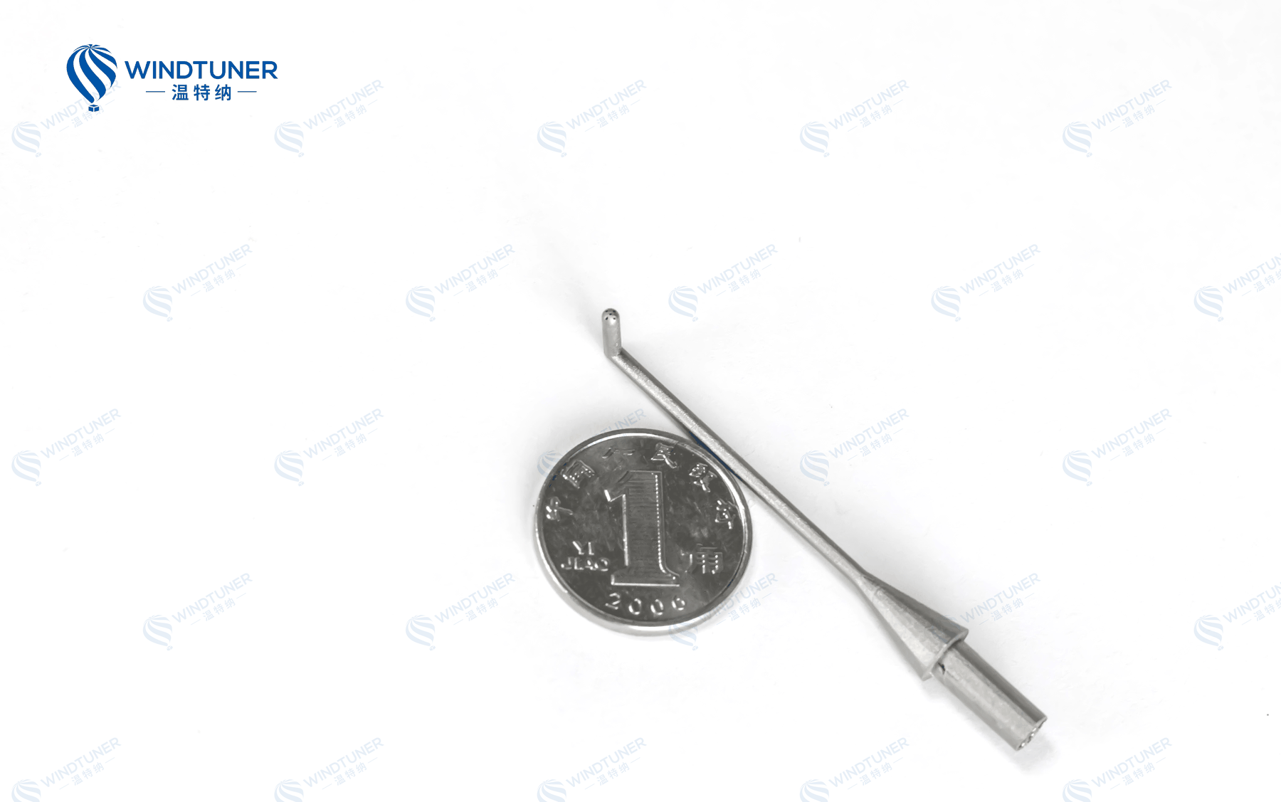
WINDTUNER has low-speed, subsonic, and supersonic calibration wind tunnels for probe and airspeed probe calibration within the applicable ranges. The facility and conditions used for a particular job depend on the probe's construction and the project requirements. A laboratory's broad speed capability does not mean that every probe is suitable for use across that entire range.
For a five-hole probe or another probe used to measure three-dimensional flow, specify the flow-angle range in each of two perpendicular planes. The zero position and positive and negative directions also need to be clear. An 'angle range' without those definitions can leave the calibration orientation inconsistent with the convention used in the measurement calculations.
WINDTUNER has low-speed, subsonic, and supersonic calibration wind tunnels for probe and airspeed probe calibration within the applicable ranges. The facility and conditions used for a particular job depend on the probe's construction and the project requirements. A laboratory's broad speed capability does not mean that every probe is suitable for use across that entire range.
Explain the Mounting Arrangement and Measurement Objective
How the probe is held and where its head points affect the calibration setup. A drawing can show the clamping location, mounting dimensions, and expected flow direction. If a specific bracket is used, explain how it fits the probe. This helps establish how the probe can be mounted for calibration and how that setup differs from its installation in the actual test.
Be specific about the measurements as well. Is total pressure the only quantity of interest, or are velocity, static pressure, and flow angles also needed? Will the results be used at a single point, or with a traverse system to survey a cross section? These details help define the calibration work and subsequent data processing. They do not mean that calibration automatically includes every function of the complete test system.
Be specific about the measurements as well. Is total pressure the only quantity of interest, or are velocity, static pressure, and flow angles also needed? Will the results be used at a single point, or with a traverse system to survey a cross section? These details help define the calibration work and subsequent data processing. They do not mean that calibration automatically includes every function of the complete test system.
Agree on the Report and Calibration Data
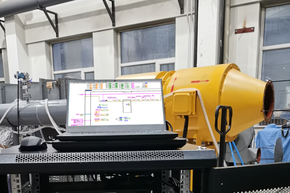
A calibration report records the relevant conditions and results. Using the probe in a test may also require calibration data or coefficients that measurement and control software uses to calculate velocity and flow angles. Ask how the data will be supplied and what speed and angle ranges it applies to, rather than asking only whether a report is included. This establishes the limits within which the results can be used.
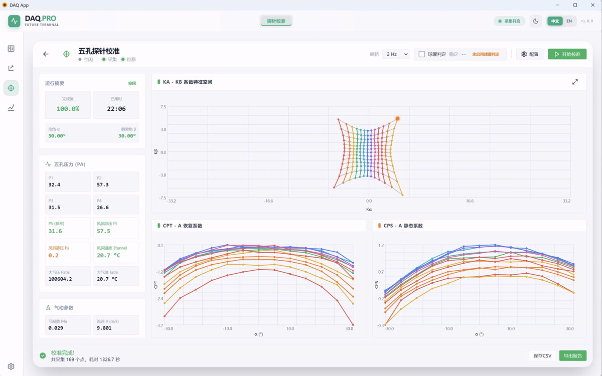
If the results will be used in existing measurement and control software, specify the required data format, units, and angle conventions in advance. A report and data suitable for software processing serve different purposes, so the deliverables should be agreed upon before calibration. Use with WINDTUNER measurement and control software should also be checked against the actual configuration, avoiding a situation where the calibration is complete but the data cannot be used as intended.
To arrange probe calibration, send WINDTUNER the probe drawings or photographs, its current condition, the operating range, and the required deliverables. Probe calibration does more than document a single test. It provides a basis for using the probe within agreed conditions and helps the test team apply the results in later measurements.
If the results will be used in existing measurement and control software, specify the required data format, units, and angle conventions in advance. A report and data suitable for software processing serve different purposes, so the deliverables should be agreed upon before calibration. Use with WINDTUNER measurement and control software should also be checked against the actual configuration, avoiding a situation where the calibration is complete but the data cannot be used as intended.
To arrange probe calibration, send WINDTUNER the probe drawings or photographs, its current condition, the operating range, and the required deliverables. Probe calibration does more than document a single test. It provides a basis for using the probe within agreed conditions and helps the test team apply the results in later measurements.