
Total Pressure Comes from Slowing the Flow
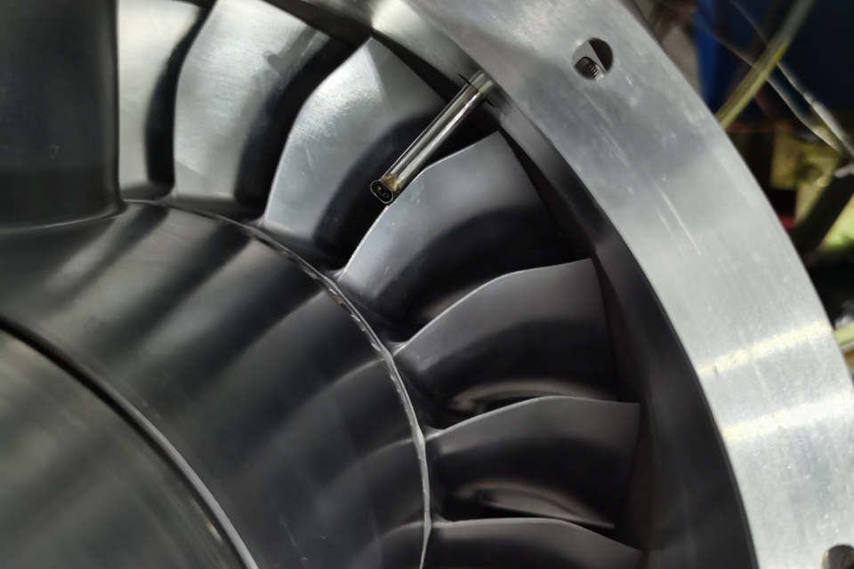
The principle is easiest to understand by looking at the small region directly in front of the probe tip. When the probe faces the incoming flow, air approaching the front pressure port slows down and, under ideal conditions, reaches a stagnation point. The pressure measured there includes static pressure and the pressure associated with the motion of the air, so it is higher than static pressure alone. In practice, total and static pressure signals are sent to pressure sensors, pressure scanners, or similar instruments for acquisition, compensation, and calculation. Total pressure is not a direct speed reading. Static pressure and the required temperature or density data must also be known, and the calculation method must match the test conditions.
Probe Alignment and Location Affect the Reading
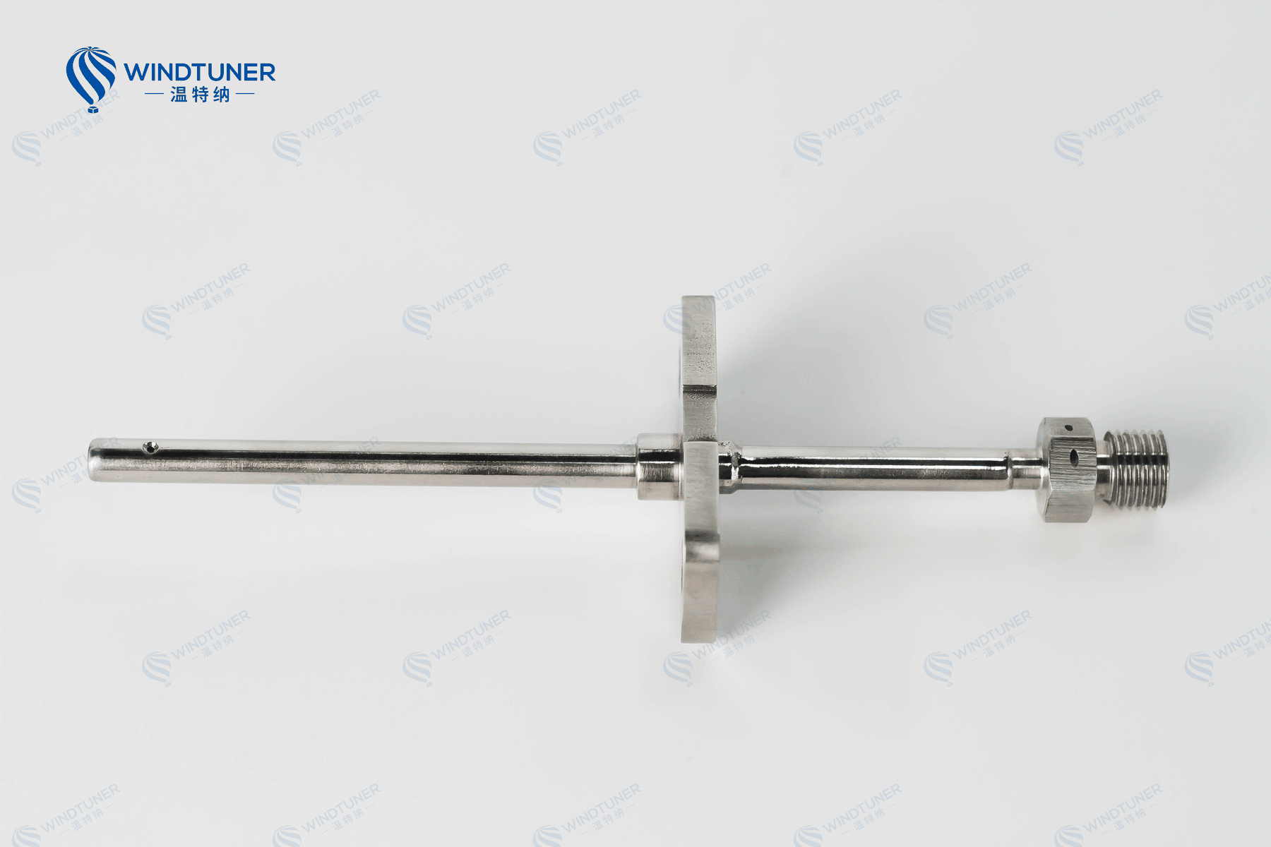
A total pressure probe should face the incoming flow as closely as possible. If the probe is set at a large angle to the flow, the pressure distribution around the tip changes and the measurement error can increase. Location matters as well. A probe placed in a wall boundary layer, behind a support, inside a vortex, or in the wake of another object may not capture representative total pressure for the intended test region. Selection therefore involves more than tip diameter. Available space, stem configuration, measurement location, expected speed range, and flow angle all need to be considered. The length and sealing of the pressure tubing, as well as any kinks or blockages, can also affect how the signal reaches the instrument.
Why a Total Pressure Probe Still Needs Calibration
Knowing the principle does not mean that every probe can use the same correction. Tip geometry, pressure-port size, manufacturing variation, and the installed configuration all influence the local flow. Calibration in a stable wind tunnel with known conditions compares the probe output with reference values and establishes data for that individual probe. If a test covers a range of speeds or flow angles, the calibration conditions should cover the intended operating envelope. The purpose is not simply to obtain a certificate; it is to understand how the measurement chain responds under the conditions in which it will be used.
From One Probe to a Complete Measurement Chain
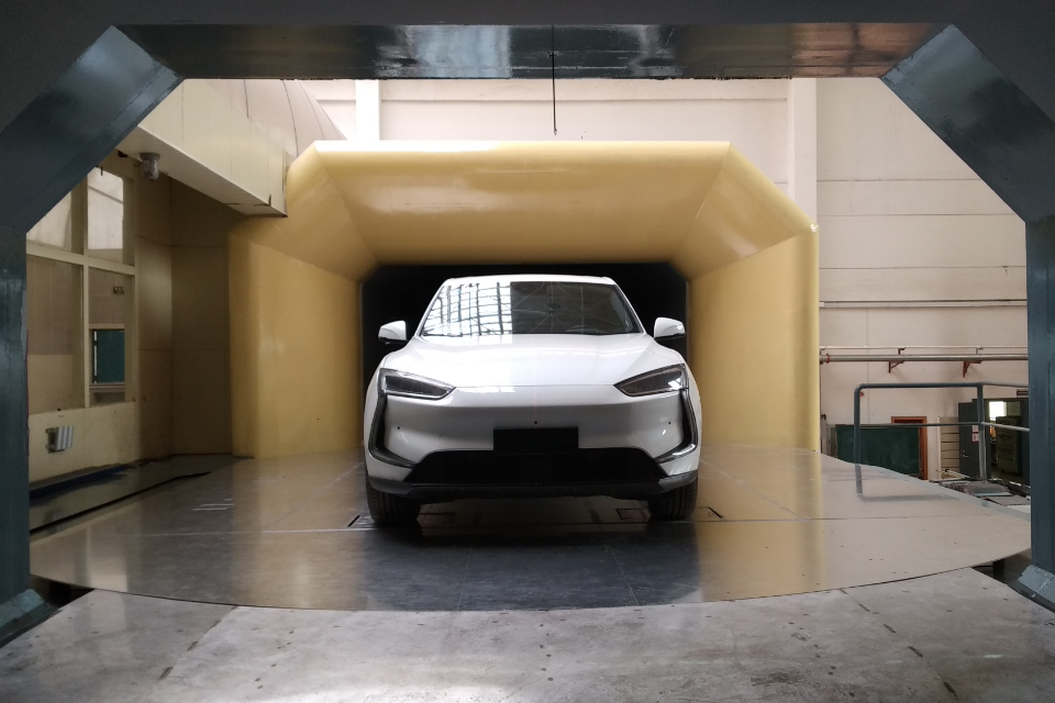
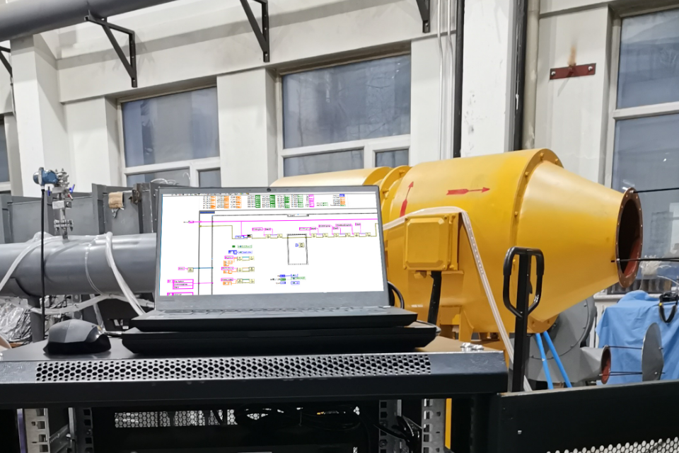
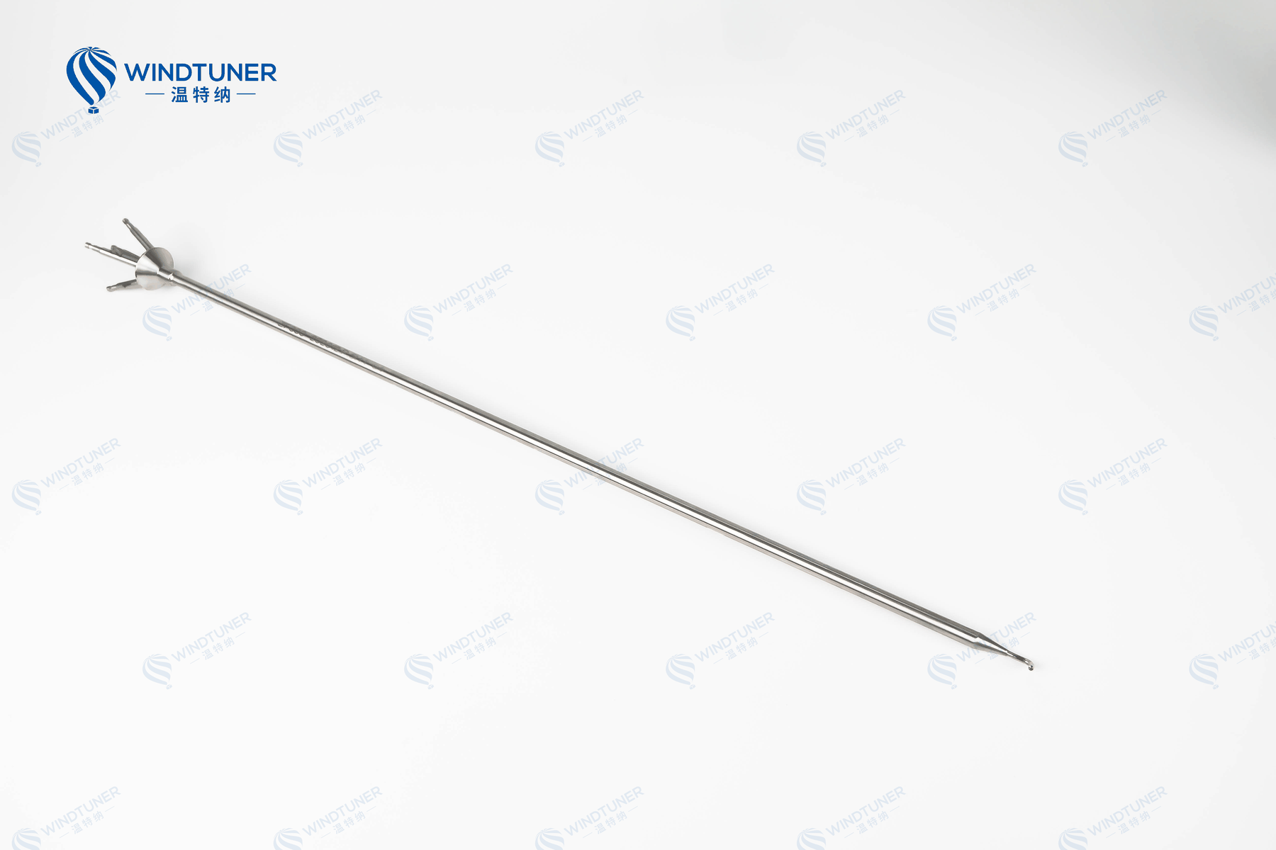
WINDTUNER customizes pneumatic probes for specific flow-field requirements. Design variables can include material, geometry, number and diameter of pressure ports, tip size, stem length, mounting configuration, range, and blockage ratio. Probe manufacturing, wind tunnel testing, and calibration can be handled as connected steps. Available products include total pressure probes, multi-hole probes, total temperature probes, high-temperature probes, and combined total temperature and total pressure probes. These can also be integrated with pressure scanners, motion control systems, and WindLabX measurement and control software to form a complete test system. The practical question is not simply whether a probe is available, but whether the measurement point, operating conditions, and data chain work together.
In operation, a total pressure probe slows the air in a controlled way at the correct location, captures the resulting total pressure, and uses static pressure and other required parameters as references for the calculation. Probe geometry, alignment, tubing, sensors, and calibration data all influence the final result. Treating these elements as one measurement chain is the best way to obtain useful data from a total pressure probe in an actual test.