
Why the Measurement Chain Must Move as One
Why must all components of a pressure system work in uniformity? Because a pressure probe in movement creates a timing problem equivalent to its positioning problem. In coordinated movement, the electric actuator must reach the designated coordinate and settle before acquisition starts. The pressure scanner must then sample each port at the correct time. Calibration coefficients have to match the installed pressure probe, while the software has to associate every pressure record with the right spatial coordinate. If any part of that chain operates on its own clock or data format, the final map can place a valid reading at the wrong location.Traditional pressure measurement system integration often leaves this work to the test engineer. One interface drives motion, another records pressure, and a separate program converts raw data into velocity and flow angle. The engineer writes scripts between them, checks trigger delays, and rebuilds the dataset after each interrupted run. This process consumes tunnel time and creates several places where a configuration error can hide.
WINDTUNER treats the sequence as one measurement task. Our combined test system defines the grid, dwell time, sampling rate, and acquisition trigger. Each coordinate becomes part of the same record as the measured pressures and calculated flow parameters. That structure makes a repeated traverse easier to compare with the first run and gives the engineer a direct route back to the raw channel data when one pressure point looks unusual.
How WINDTUNER Connects Motion, Pressure, and Software
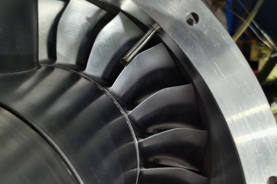
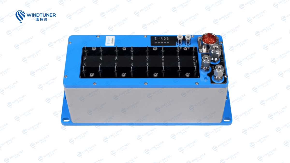
The pressure probe is the section where the measurement system begins to meet the flow. WINDTUNER designs three-hole, five-hole, seven-hole, and other pneumatic probes for the geometry, angle range, blockage limit, and mounting constraints of the test section. For a three-dimensional survey, a calibrated five-hole probe can resolve velocity and flow direction from five pressure ports. The electric actuator then carries that probe through the programmed measurement plane with repeatable linear or rotary motion.At each position, a WINDTUNER pressure scanner acquires this flow field data from probe channels. A standard unit provides 16 separate channels with 24-bit A/D resolution, an adjustable sampling rate up to 500 Hz, and ±0.05% FS accuracy. Software, hardware, and timed trigger modes fit different rig sequences. IEEE 1588V2 time synchronization keeps distributed units on a common time base when the wind tunnel measurement system expands beyond one scanner.
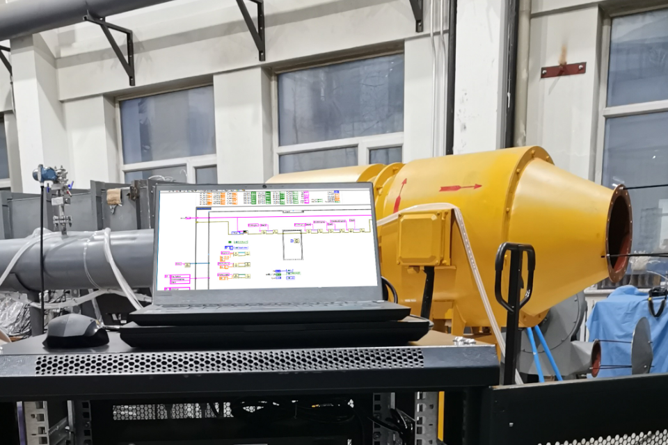
WindLabX is our Labview software that runs device management, motion commands, pressure acquisition, calibration data, and parameter calculation from a unified operating environment. Its flow field mapping module converts the coordinate-linked measurements into a visible plane. An engineer can inspect a velocity deficit in a wake, a flow-angle shift behind a cascade, or non-uniformity at a tunnel exit without exporting several files and rebuilding the position history themselves.
Calibration Closes the Loop Before the First Run
Integration only works when the coefficients and instruments share a traceable calibration path. WINDTUNER operates a calibration wind tunnel laboratory accredited by CNAS under an ISO/IEC 17025 management system. We calibrate pneumatic probes across the required angle and speed range, and our pressure laboratory calibrates pressure scanners and digital manometers. The same team can review probe geometry, scanner range, actuator travel, and software configuration before hardware reaches the client.This closed loop matters when a test changes. A new model may move the measurement plane, narrow the available mounting space, or push the expected flow angle beyond the original pneumatic probe range. WINDTUNER can revise the probe, update the traverse plan, load the matching calibration data, and keep the rest of the measurement chain intact. The client does not have to restart integration with several vendors.
A wind tunnel measurement system has most value in the hours between tunnel startup and a defensible flow map. WINDTUNER manufactures and calibrates measurement instruments, connects them through WindLabX, and delivers the sequence as one working measurement chain. Engineers spend less testing time reconciling pneumatic probe hardware and more time reading the flow field they set out to measure.