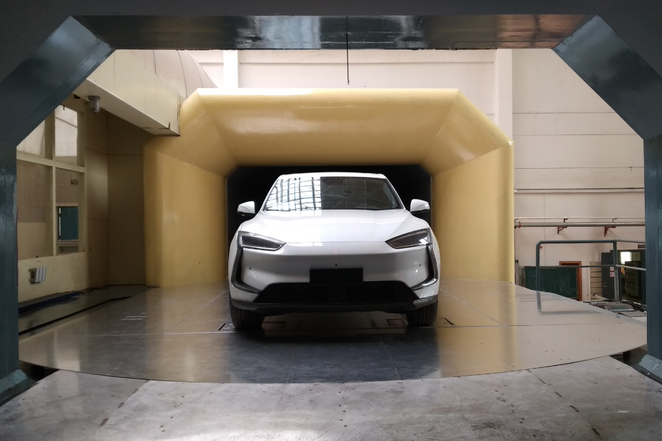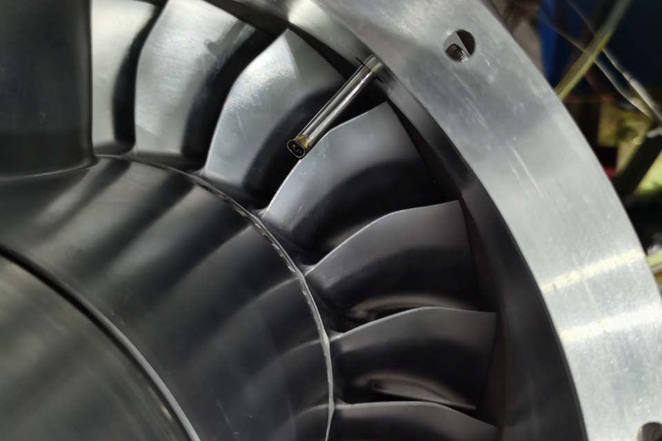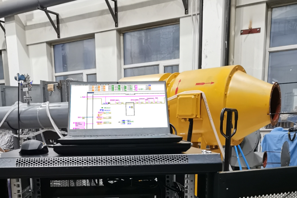

Windtuner pressure scanners capture the unsteady pressure field in transonic compressor tests. The hardware handles the measurement frequencies, spatial resolution, and accuracy that transonic aerodynamics demand.
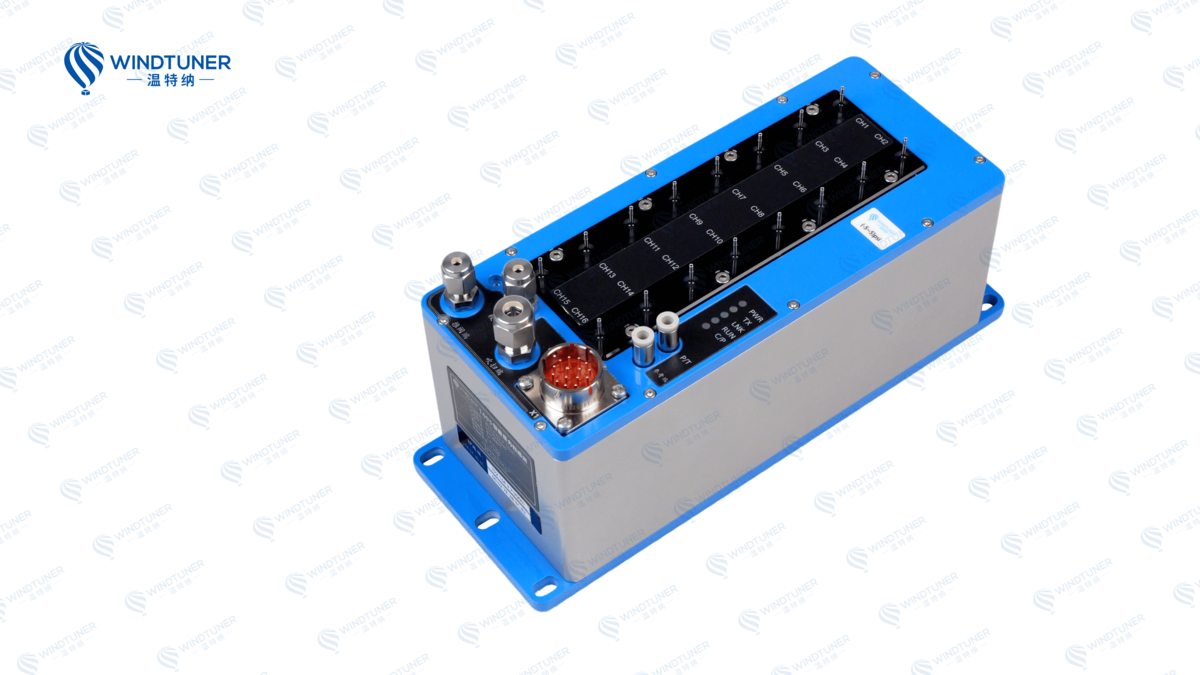
Windtuner Pressure Scanners Capture the Complicated and Subtle Movement in Complicated Flow Fields
Where Transonic Flow Creates Measurement Challenges
A transonic compressor blade sees shock waves, separated flow, and unsteady wake interaction all at the same time. The pressure field is not steady. Rotor-stator interaction generates periodic pressure fluctuations at blade passing frequency. Shock motion drives broader-band unsteadiness. Rotating stall and surge add low-frequency components. A measurement system that averages out the unsteady content misses the physics. The engineer needs time-resolved data at enough locations to reconstruct the flow field.Spatial resolution matters as much as temporal resolution. A shock wave on a transonic blade can be less than a millimeter thick. The pressure rise across the shock happens over a distance shorter than the spacing between static pressure taps. If the measurement grid is too coarse, the shock appears smeared out, and the boundary layer separation downstream of the shock cannot be diagnosed. Windtuner manufactures pressure scanners with up to 128 channels per unit, so the engineer can cover the blade surface and the annulus without running separate test campaigns.
Accuracy tightens the measurement even further. A transonic compressor operates close to its stability limit. The difference between stable operation and rotating stall can be a one-percent change in pressure rise. If the scanner drifts by more than that during the test, the engineer cannot tell whether the compressor behavior changed or the instrument shifted. Windtuner pressure scanners hold ±0.05% FS accuracy, which keeps the measurement steady through thermal cycles and long-duration testing.
How Modern Compressor Tests Use High-Channel-Count Scanners
Transonic compressor tests increasingly rely on high-channel-count pressure scanners networked together. A fan rig test might use ten scanners with 128 channels each, measuring 1,280 pressures simultaneously. The data streams synchronize via IEEE 1588V2 time protocol, so the entire pressure field resolves at 500 Hz or higher. The engineer sees the shock position, the wake passing events, and the onset of stall precursors in real time.Windtuner has supplied pressure scanners for transonic fan tests at engine manufacturers and research labs. The scanners run for weeks at a time, capturing data through speed sweeps, throttle transients, and stall recovery maneuvers. The built-in pneumatic calibration system corrects for temperature drift without stopping the test. The engineer focuses on the compressor, not on babysitting the instrumentation.
The measurement density that modern scanners provide changes what is possible in transonic testing. Twenty years ago, an engineer might instrument twenty locations on a blade and interpolate the rest. Today, the engineer instruments two hundred locations and resolves the shock structure directly. The boundary layer state upstream and downstream of the shock becomes measurable, not inferred. Flow separation at part-speed conditions shows up in the data instead of being discovered during engine integration.
That measurement capability feeds directly into compressor design. When an engineer sees exactly where the shock sits on the blade and how the boundary layer responds, the aerodynamic model improves. When the model improves, the next blade design gets closer to the performance target. Transonic compressor development moves faster when the measurement system keeps up with the aerodynamics.