
Raw Pressure Is Only the Starting Point
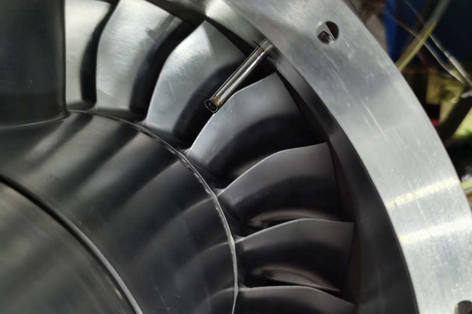
A five-hole probe consists of five pressure ports, producing five pressure readings. At probe stage, the system still has no velocity vector or flow angle. Thus we need to rely on WindLabX to read the pressure ratios against calibration surfaces made for the individual probe. A coefficient set built from another head geometry, or another Mach range, can produce a clean-looking answer that is still wrong.The mix-up is easy to make in a laboratory with several probes that look alike. Many kinds of inconsistencies occur when, for example, a file lands on the wrong workstation, the channel order is changed, or when a wrong probe can fit into the mount. What makes things worse is that during these occur, the pressure scanner can keep returning steady numbers. Raw channels do not warn the operator about a mismatched coefficient table. A lot more time and effort is wasted if the pressure measurement inconsistencies are first discovered after the tunnel run.
Calibration Must Follow the Physical Probe
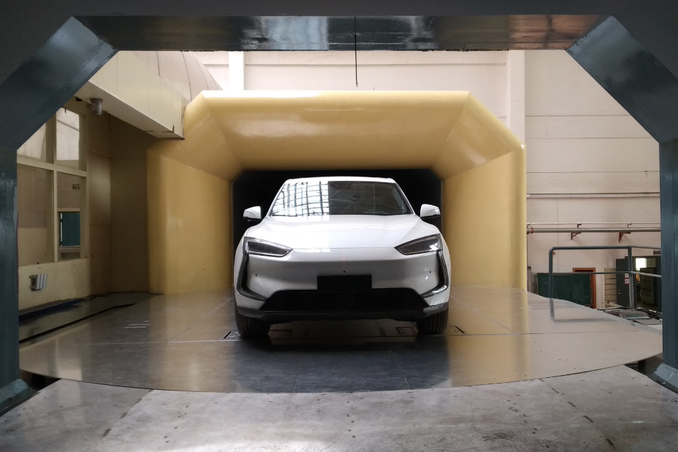
WINDTUNER runs pressure probe calibration in our calibration wind tunnel laboratory, which is accredited by CNAS and operates under an ISO/IEC 17025 management system. Probe type and operating range determine the tunnel and test matrix. A three-hole probe can measure two-dimensional flow up to Mach 2 across angles of up to 30 degrees. For wider angular coverage, a 14-hole probe measures all-directional flow up to Mach 0.95 and angles up to 160 degrees.During calibration, each known flow condition produces a set of pressure coefficients. We keep those coefficients with the probe customization, configuration and specified range. The details are not cosmetic: Port diameter and head shape change the response; stem layout, material, and surface finish can change it too. Two pneumatic probes built for the same job still require separate records when the client needs angle and velocity data that stand up to review.
The Pressure Scanner Keeps Every Channel Accountable
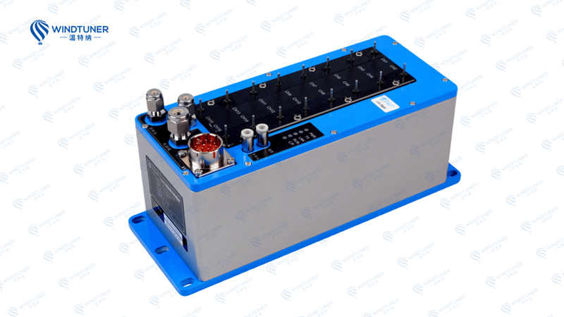
The WINDTUNER pressure scanner is the base for calibration data. Every unit of this pressure DAQ instrument has 16 channels to read with 24-bit A/D resolution and adjustable sampling up to 500 Hz. Accuracy is ±0.05% FS. The test rig can start a sample through software, hardware, or a timed trigger. On rigs with several scanners, we implement IEEE 1588V2 to put every unit on the same clock.Channel mapping needs the same care as pressure instrument calibration. Probe port one has to remain on its assigned scanner channel, and each channel range must fit the expected pressure. WindLabX saves the device setup with the task. The calculation no longer rests on a handwritten wiring note beside the rig. When maintenance moves a tube or channel, the engineer updates the assignment before testing resumes.
WindLabX Turns Traceability into Flow Data
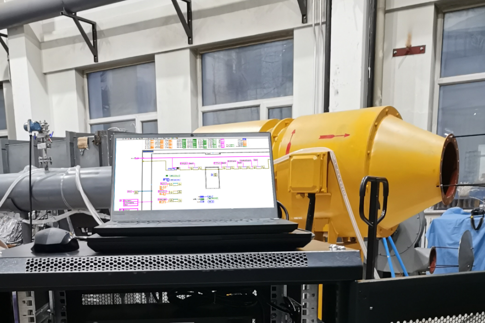
Inside our LabVIEW control software WindLabX, pressure probe coefficients meet pressure scanner readings, ambient references, and test coordinates. The pneumatic probe module calculates velocity and flow angle from the active channels. Its mapping module places the result at the measured location. Pressure data acquisition and the coefficient calculation stay in the same record, so engineers do not have to rebuild that relationship in a separate file.An odd point is easier to investigate when its trail remains intact. Engineers can open a sudden angle change and check the five source pressures, the coefficient region in use, and the recorded probe position. That evidence separates a flow feature from a plugged port, a bad range choice, or a setup error. The next pressure acquisition run can test a diagnosis instead of quietly replacing one suspicious value.
A pressure measurement chain is trustworthy when every calculated result can be followed back to the probe and its calibration. WINDTUNER manufactures the pressure probe, calibrates it in our own pressure laboratory, acquires its channels with a pressure scanner, and processes the coefficients in self-developed measurement and control software. That continuity keeps calibration data attached to the hardware and gives clients flow results they can defend.